Testing MOLONARI in the lab
To test the MOLONARI device and the data-processing algorithms in the laboratory, we set up two mock-ups. The first is a column that makes it easy to determine the porous-medium parameters (porosity \(n\), permeability \(K\), thermal capacity \(c_m\)) by controlling the water flow rate. The second, a larger-scale mock-up, allows full integration of MOLONARI with the sensor rod and the control unit.
The porous material used is an arrangement of small beads of various diameters (2mm, 5mm and 7mm).
Summary
The column mock-up
Testing the porous material and the inversion algorithm
The column offers several practical advantages:
- It allows easy control of both the flow rate and the column height, which is particularly useful for the Darcy column experiment;
- It is quick and easy to build: starting from the bare plexiglass tube, it takes only about 2 hours to assemble the full setup described below;
- Its low cost and ease of assembly make it possible to perform multiple tests, since it is not an issue if the column is damaged or destroyed. This also allowed us to carry out pseudo-2D tests.
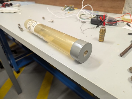
A. Building the column
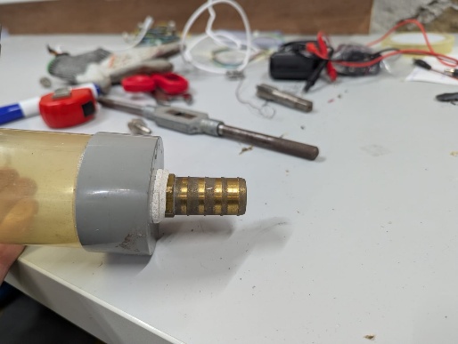
The base of the column is a 40 cm-high plexiglass tube, sealed on one end, which is pierced using a soldering iron in order to insert a threaded connector. Ideally, the hole can be tapped to match the connector size, but the connector can also be force-fitted while the plastic is still hot. We also added sealing gaskets around the connector.
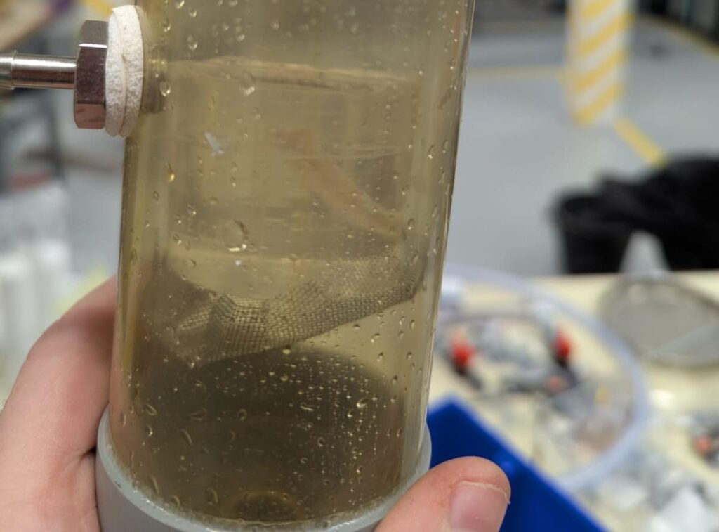
We then added a filter at the bottom of the column to prevent the beads used in the experiment from escaping. To do this, we cut a circular piece of filter material slightly larger than the inner diameter of the column and made small notches along its edge so it could fit snugly against the walls. A round object was used to properly push the filter down to the bottom of the column.
B. Building the sensors device
Since the MOLONARI system is obviously too large to fit inside the column, we had to adapt it for this mock-up.
- We used a thin metal rod to which we taped the four temperature sensors and a small tube used to measure the pressure at the bottom of the column (note: hose clamps would be preferable, as they are more resistant to water).
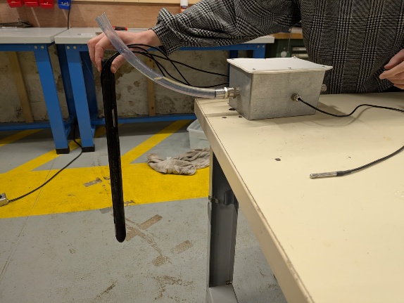
- The differential pressure sensor was split into two parts: the membrane was coated in silicone so it could be immersed in the column, while the electronic module was placed outside the column due to space constraints. The differential pressure sensor was calibrated at room temperature to obtain the law \(\Delta h = f(U)\), with \(f(x) = 39.804x – 41.978\).
As no homemade data loggers were available at the time we built this mock-up, we used Hoboware data loggers to record the measurements.
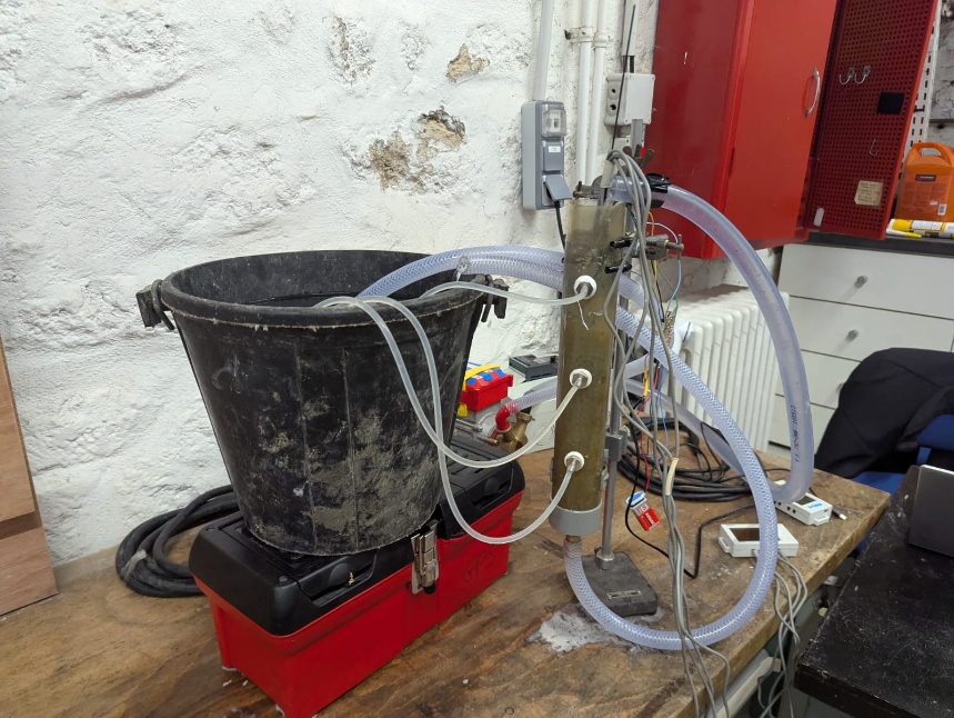
C. Setting up the mock-up
The column is then integrated into a hydraulic circuit to simulate water circulation. A tube runs from the bottom of the column to drain into a large buffer tank, which makes it easier to maintain steady-state conditions. The pump draws water from this tank to supply the top of the column. It is important that the water level in the buffer tank and in the column be at the same height so that, under steady-state conditions, the flow rate corresponds to the head loss in the column, allowing Darcy’s law to be applied.
The sensor rod is then installed inside the column, after which the mixture of beads is poured in. The column can then be filled with water.
The pump must be adjusted to reach steady-state flow. Note that, to initiate the hydraulic circuit, it is necessary to increase the pump frequency above the steady-state value.
D. Determination of \(n\), \(K\) and \(c_m\)
Porosity is determined by measuring the mass of a given volume of beads outside of water and the mass of that same volume of beads filled with water. Since porosity is defined as the ratio between the volume of water and the total volume of beads plus water, it can be obtained by knowing the mass of beads used, the mass of added water, and the densities of both materials. With a mixture consisting of 30% beads of 2 mm diameter and 70% beads of 7 mm diameter, we obtain a porosity of 34%.
Permeability is determined by applying Darcy’s law, which relates the flow rate in the column, the column height, and the head difference. The head difference is measured with the differential pressure sensor, while the column height corresponds to the height of the porous material. The flow rate can be easily determined by placing a container at the outlet of the tube connected to the bottom of the column and measuring the filling time. Note: to maintain the same operating conditions, the volume of water in the buffer tank must be much larger than the measured volume—i.e., the water level in the container should hardly change during the measurement. It is also necessary to ensure that the height of the outlet tube used for measuring the flow rate remains constant. For the same bead mixture as above, we obtain an intrinsic permeability of \(3.1 \cdot 10^{-9} m^2\).
Finally, the thermal capacity of the medium is obtained using simple calorimetry experiments. The glass making up the beads has a heat capacity of 2300 J/kg/K.
E. Pseudo-2D
With the aim of performing measurements involving a source term—that is, an intermediate gain or loss of thermal energy—we decided to drill three holes in the column. These holes create leaks and therefore make it possible to model heat loss toward the sides of the river.
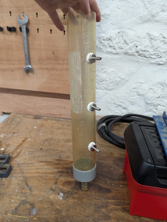
The holes were made using a soldering iron and then tapped to accommodate the threaded fittings. Again, we used sealing gaskets to reduce leakage. Note that resin could also be used to achieve perfect watertightness.
The leaks created in this way are directed toward the buffer tank using small tubes. The column can be returned to a 1D system by tying a knot at the end of these tubes.
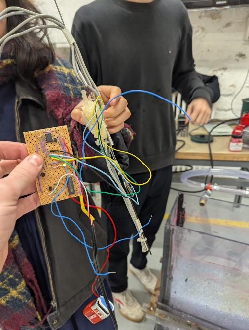
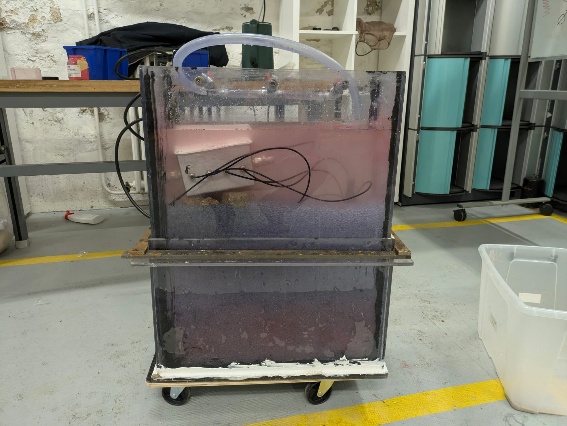
Testing the MOLONARI device
In order to test the MOLONARI system (photo below) as it was designed—that is, with the sensor rod and the control unit for data recording and transmission—it was necessary to build a larger-scale mock-up.
A. Building the mock-up
The mock-up is made of nine plexiglass panels bonded together with resin: four panels are attached to a fifth one, which serves as the base of the mock-up, using resin, and the remaining four panels reinforce the lower part of the side walls. The entire assembly is bonded with resin, and the interior corners are sealed with gaskets, as is the exterior base of the mock-up.
To strengthen the mock-up compared with last year’s version so that it would not fail under pressure, we decided to reinforce it using metal bars that we drilled and screwed together. This helps to limit deformation of the mock-up walls.
Finally, to allow water circulation, three holes were drilled at the top and at the bottom of the mock-up so that threaded fittings could be installed. The three bottom fittings were sealed to ensure watertightness. Filters were glued inside the mock-up at the level of the bottom fittings to prevent the porous material from entering the pump.
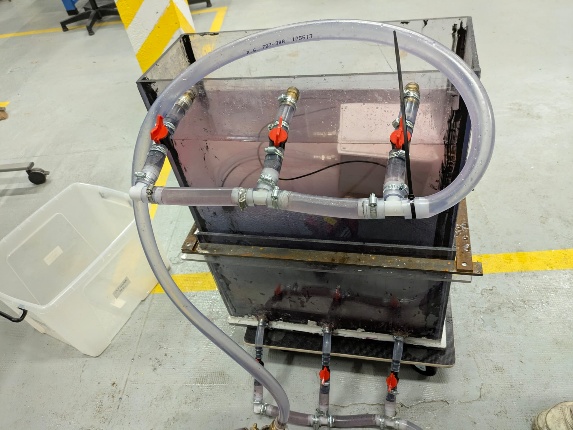
B. Setting up the mock-up
Water circulation is provided by a pump. The three upper fittings are connected in parallel with valves to control the flow rate in each branch. A similar setup is used at the bottom.
The mock-up is then filled with glass beads of different diameters (2 mm, 5 mm, 7 mm) and subsequently flooded. The circulation flow rate is adjusted by changing the pump frequency.
Finally, the MOLONARI rod is pushed into the medium by applying force and gently tapping it with a mallet.
Water flow patterns—especially hot-water plumes—can also be visualized in the mock-up using a thermochromic pigment.
C. Pseudo-2D
A pseudo-2D circulation can be established in the mock-up by leaving only one valve open at the top and one at the bottom. The two open valves must be positioned opposite each other—for example, the upper left valve and the lower right one.